A typical enquiry can start quite simply:
“Can you provide a 700 × 700 mm hatch that opens at a certain load?”
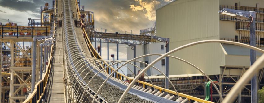
But when the hatch is to be installed beneath a conveyor or conveyor system handling wet sand, slurry, or other materials, the starting point needs to be different.
A load-triggered safety hatch is not simply a standard hatch installed upside down. The solution needs to be designed around what should happen in a fault condition, the geometry of the opening, how the material should be discharged, and how the hatch will be reset afterwards.
Start with the function
Before deciding on hinges, gas springs, or electric actuators, the actual operating scenario needs to be defined.
Should the hatch:
- open automatically when a certain load is reached?
- be opened manually after the system has been shut down?
- discharge material?
- relieve pressure?
- or be used for access and maintenance?
A hatch designed to open due to a build-up of wet sand has different requirements from a hatch designed to open under gas or vapour pressure.
A downward-opening hatch behaves differently
A standard floor hatch opens upwards, with gravity helping to keep the cover closed.
When the hatch is instead installed beneath a conveyor or conveyor system, gravity acts in the opening direction. This means that locking, restraint, controlled opening, and resetting need to be handled differently.
The solution may, for example, require project-specific locking arrangements, secondary restraint, hold-open devices, or assisted operation to prevent uncontrolled downward movement.
The reset procedure also needs to be considered. Depending on the installation, access from below or specific working equipment may be required.
Do not look at the 700 × 700 mm dimension alone
Three different dimensions need to be considered during design:
Structural opening
The actual opening in the conveyor, conveyor system, or surrounding steel structure.
Overall size
The total footprint required for the frame, hinges, fixings, and operating hardware.
Clear opening
The usable free opening when the hatch is fully open.
Frame profiles, hinges, safety grids, gas springs, and electric actuators can all reduce the clear opening. A nominal hatch size should therefore never automatically be assumed to equal the usable clear opening.
A dimensioned general arrangement drawing should always be used to verify the final solution.
Define the opening principle early
There are four main principles:
Load-triggered – the hatch opens automatically when the retained material reaches a defined load.
Pressure-triggered – the hatch opens automatically to relieve gas, vapour, or internal pressure.
Manual quick release – the operator opens the hatch after the system has been shut down and the area has been made safe.
Hybrid or assisted solution – mechanical locking is combined with, for example, electrical or hydraulic assistance for controlled opening or resetting.
If the solution also requires limit switches, local controls, or 24 V DC operation, this should be defined early in the design process.
Wet sand does not behave like water
Water and other liquids generally distribute pressure relatively evenly. Wet sand, on the other hand, behaves as a bulk material.
It can compact, bridge, and transfer part of the load into surrounding structures through friction. The load acting on the hatch therefore cannot always be calculated as a simple vertical column of material directly above the opening.
Two different material considerations also need to be distinguished:
Corrosion resistance – for example, stainless steel EN 1.4404 / 316 may be suitable in wet or aggressive environments.
Abrasion resistance – where abrasive material is discharged repeatedly, additional wear parts, protective surfaces, or deflectors may be required.
Also consider the area below the hatch
Getting the hatch to open is only one part of the solution.
You also need to consider:
- what is located directly below the opening,
- whether discharged material could hit walkways, pipework, or steelwork,
- whether a chute, deflector plate, or other guide is required,
- how surrounding surfaces may be affected by abrasion,
- and how the hatch will be reset and secured after discharge.
A complete safety solution therefore needs to cover the full sequence – from triggering through to safe reset.
Information required for technical assessment
To assess and design the right solution, we primarily need:
- the material being handled,
- expected material build-up or trigger load,
- structural opening,
- required clear opening,
- installation orientation,
- surrounding structures and possible clashes,
- environmental conditions,
- what is located below the opening,
- and how the hatch will be reset afterwards.
Marked-up sections, drawings, or BIM screenshots are particularly useful.
The clearer the project conditions are from the start, the easier it is for us, together with our manufacturer, to assess whether the solution should be designed as a bespoke hatch, release panel, assisted-opening solution, or another project-specific arrangement.
Frequently Asked Questions
Structural opening is the physical aperture cut into the steelwork. Clear opening is the usable free space to pass material, equipment, or personnel through once the hatch is open. Overall size is the full footprint including the outer frame and operating hardware.
Yes, but inverted installations change the brief significantly. Standard assumptions around gravity, assisted opening, and maintenance access no longer apply in the same way. Retention, restraint, and reset all need to be considered specifically for the underside installation.
Not necessarily. Heavy-duty frames, hinges, safety grids, gas springs, and actuators all take up space. That is why a nominal size or structural opening should never be assumed to equal the usable clear opening. Always check the General Arrangement drawing.
No. Wet sand behaves as a bulk solid. It can bridge, compact, and transfer load into surrounding surfaces rather than flowing like a simple liquid head. Wall friction, cohesion, and abrasive wear all affect how the release condition should be assessed.
Potentially, but the trigger basis must be defined first. A hatch that releases under retained material load is not the same as one that opens under internal pressure. Each needs its own engineering basis, restraint logic, and reset method.
Send the material, likely build-up or trigger condition, structural opening, clear opening required, installation orientation, nearby clashes, what sits below the opening, environmental conditions, and how the hatch will be reset afterwards.
Marked-up sections or BIM screenshots are ideal.